The Multiple Station, Firework Fire Control Board
|
AUTHOR’S NOTE: This project does not require any special electrical engineering knowledge, but there is a significant amount of labor involved. Attention to detail, patience, testing, and neatness are essential to a successful end result.
I would rate this project as INTERMEDIATE to EXPERT in difficulty. This is mainly due to the number of parts involved and the amount of wiring required.
Please also be aware that I am not an electrical engineer. (Anyone who is, will look at my work and probably cringe). However I did design, build, test, and utilize this for my 4th of July show. I know for a fact that this project / design works, but I make no guarantees about yours. I also hereby absolve myself of any and all liability if you make one yourself. The quality of the construction and the safety of using this system is solely yours and yours alone.
This design is the sole property of the "Author", Matt Teemer. You may not publish, reproduce, claim, modify or manufacture for commercial use, the device or the plans described herein. The Author grants the individual right to the public to utilize these plans for the purpose of constructing the device described here-in for individual personal use only. By utilizing these plans, you are agreeing to the conditions and liability as described above.
|
The following pages will document the design, construction, and use of a custom built, fire control board used for firework detonation. I will itemize in detail all the parts and their costs used in this project including links to online parts suppliers used. I will also cover the background and research that led to the final design. Step by step instructions including photos will be provided for each phase of construction.
|
First let’s discuss the motivation for building this system. I live in the state of Washington where we can legally purchase and fire 1.5" mortar fireworks without any special licensing (depending on county and city ordinances). Last year (2007) for the 4th of July, several friends and I got together to put on a show for our families.
We purchased several hundred mortar rounds and constructed three, twelve shot, launch stations. Each station consisted of 12 cardboard launch tubes (provided with the fireworks) at each station, anchored to wood bases to provide stability and safety.
We tested multiple firing methods during the course of the night. We had some mortars "wired" together with fuse into 4 shot and 12 shot clusters so we could light one fuse and set off multiple shells in quick succession. We discovered that wiring the shells together was a very tedious and time consuming process and not terribly efficient (we pre-wired the shells before the display started). We also fired about half the shells individually. For all the shots fired we used propane torches to light the fuses by lighting the 2 foot fuses quickly and then stepping away. Needless to say this was not ideal and it was all we could do to keep the show going without major interruptions even with 3 people / stations loading and firing in rotation.
Due to the overwhelming success and popularity of the show, we elected to scale up quite a bit for 2008. This increase in the number of shells we were going to fire and our desire to have a more fluid show, required a more efficient and safer firing solution. Enter the E-Match and the fire control board.
|
As I did research on better solutions, and what the professionals used, I discovered the E-Match and the associated fire control boards used to ignite them. The following is an excellent definition of what an E-Match is and how they work. It is taken from http://www.skylighter.com (whom we highly recommend you use for all your firework supplies):
|
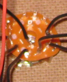
"At the heart of each e-match is a very thin nichrome wire bridging a small gap on the leading edge of a chip cut from circuit board material. This nichrome wire is soldered to the chip on both sides of the gap. When an electrical current is introduced to the wire, it heats up and melts. The heat from the melting wire then ignites one or more layers of pyrotechnic material ("pyrogen") coating the tip of the e-match. It is this ignition, which creates the characteristic pop or snap sound of the e-match explosion.
An e-match can be used only one time. Once they are made, they are fairly safe to use and handle. The small explosion made by an e-match is about the same power as a toy cap. But they are friction and impact sensitive, so some care should be taken in using them with fireworks or around black powder and other explosive compositions."
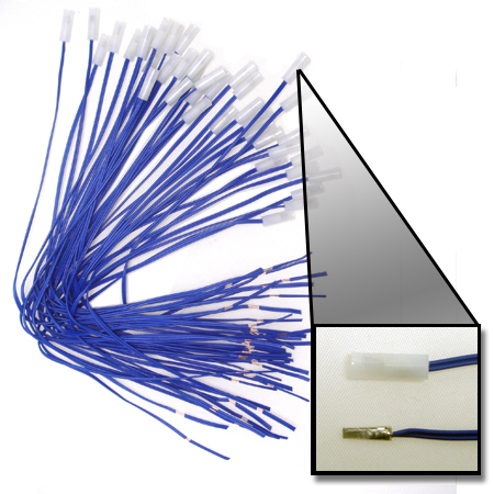
The above image is of a typical E-Match with a protective plastic sheath.
Image courtesy of http://www.skylighter.com
|
E-Matches require a current to be passed through the lead wires in order to melt the nichrome wire and ignite the e-match. A typical E-Match requires 1 volt DC per E-Match on a circuit, plus 3 volts for each hundred feet of 24 gauge cabling and shot wire.
You can detonate E-Matches by simply connecting the leads to wires and then attaching those wires to a sufficiently powerful battery. This however is not an ideal or efficient firing solution. If you are going to fire 1 or 2 shells at a time, just use fuse and a lighter. The proper solution for large scale displays is the use of a fire control board.
A decent fire control board available on the general market typically has 10-12 cues. These multiple cue systems generally consist of the fire control board and a remote firing board. These two components are typically connected via wires or in a more elegant solution via data cables such as a 25 pin computer serial cable.
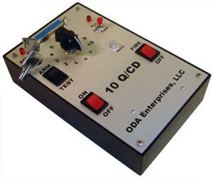
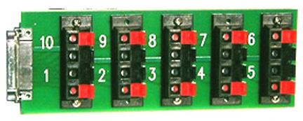
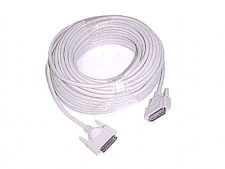
The above images courtesy of http://www.skylighter.com
The solution described above (and shown in the pictures above) would cost you $398.57. This would provide you with a single 10 shot board. You could use multiple boards and cables and attach them one at a time to get more shots per setup. This would entail an additional cost of $115.12 per remote station.
In the course of my research I found that this was a typical cost for a quality product with this capacity. Higher capacity units were also available but quickly increased in cost. For example I found a 35 cue unit that was very well built and is contained in a weatherproof case but it came at a cost of Ł999.95 ($1,958.00)
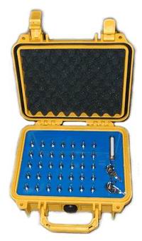
Images courtesy of http://www.brightonfireworks.com
|
Now I am an avid pyrotechnic hobbiest but I am not doing this for a living and the idea of paying thousands of dollars for a multi cue system was a little out of the question. The cheaper solutions did not really provide the number of cues and firing stations desired and honestly for what they are, were a little pricy themselves ($40.00 - $60.00 per cue).
So the next natural course of thought leads to: "I can build something better than these and do it a lot cheaper!". My research at this point shifted from shopping for a solution to searching for plans / ideas on how to build my own.
Of all the "home" projects I found the following was the cream of the crop and provided some useful ideas for what I ultimately ended up designing:
|
Joe Zastrow's Firing System:
http://www.pyrouniverse.com/show/firingsystems/joe.htm
http://www.pyrouniverse.com/show/firingsystems/joe2.htm
http://www.pyrouniverse.com/show/firingsystems/joe3.htm
|
So the first thing I did when designing my system was think about what I wanted out of my system:
- I wanted the system to be relatively compact and self contained
- I wanted to mount the system in a case to protect it and to make it look better
- I wanted the system to be expandable
- I wanted the system to have a high potential capacity
- I wanted the system to have a decent level of functionality
The next thing I needed to figure out was the capacity of the system. The Fireworks we usually buy come in packs of 12 mortars and we found through our experiences last year that 12 shots per station is an easily manageable amount. It was also important that we have multiple stations for several reasons:
- Safety – By having multiple stations, we can allow time for the tubes to cool down prior to reloading thus reducing the chance of accidental firing between shots.
- Continuity – Multiple stations allow us to be firing one station while the station used before that is cooling off and the one before that is being re-loaded. This keeps the show moving without interruption.
- Variety – Having different types of shells loaded in different stations allows us to orchestrate the show on the fly.
Based on the number of shells we plan to fire this year, the number of people assisting us, and several other factors, I decided that we would have 24 shots (cues) per station with a total of 6 remote stations. This gives us a potential of 144 shots (cues) assuming all tubes are loaded.
The next step was deciding on the layout and general functionality of the system. I decided the following features were essential:
- The fire control board would need 6 DB25 (25 pin data cable) hook ups. One for each of the 6 remote firing stations
- We would use 50 foot DB25 cables to attach the fire control board to the remote stations
- The system needed to provide both a built in continuity test per cue as well as a dedicated firing button per cue.
- The system should use one power supply for continuity testing and a separate supply for firing. These power supplies should be economical and easily replaced.
- There needed to be 1 power switch for continuity testing controlled by a locking key switch
- There needed to be 1 master fire control / safety switch controlled by a locking key switch
- The system would use a 6 position selector switch to determine which of the 6 remote stations was being controlled at any given time
- The case for the fire control board and the enclosures for the remote firing stations needed to be as water / weather proof / resistant as I could make them. (it is not unusual for us to get rain etc on the 4th of July in Washington)
- The entire system should be made of the best available parts to ensure quality, durability and overall esthetics while keeping the overall cost as reasonable as possible.
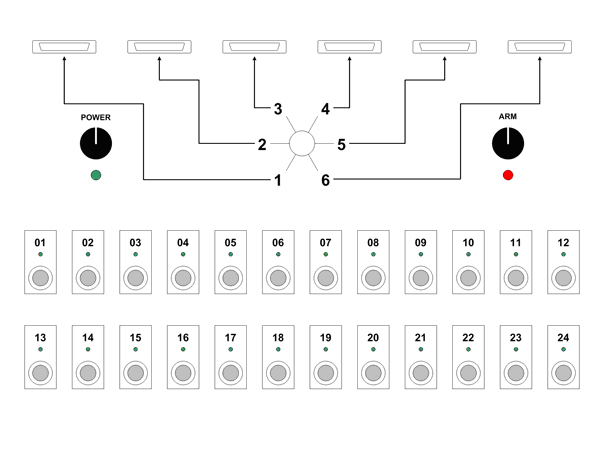
This is a rendering of the final design. The Panel is 20.00" x 15.25" This size is specific to the case it is mounted in.
|
The following is a detailed list of all of the parts used in this project along with URL’s where they can be purchased (NOTE: Many of the electrical parts listed from Radio Shack can be purchased from other vendors for cheaper. I used Radio Shack because it was easy and fast):
| Main Control Board |
Radio Shack
http://www.radioshack.com |
| Part Number |
Quantity |
Description |
Price |
Total |
| 276-1548 |
12 |
25pin D-Sub Connector |
$1.99 |
$23.88 |
| 274-680 |
2 |
12 Position European-Style Mini Terminal Strip |
$2.59 |
$5.18 |
| 274-656 |
2 |
2 Position Dual-Row Barrier Strips |
$2.29 |
$4.58 |
| 275-1386 |
1 |
6 Position Rotary Switch |
$2.99 |
$2.99 |
| 275-646 |
24 |
SPST Red Push Button Switch |
$2.49 |
$59.76 |
| 276-270 |
1 |
Red Power Indicator LED |
$1.99 |
$1.99 |
| 276-271 |
1 |
Green Power Indicator LED |
$1.99 |
$1.99 |
| 276-080 |
24 |
5mm LED Holder |
$1.49 |
$35.76 |
| 276-022 |
12 |
5mm Green LED (2 Pack) |
$1.49 |
$17.88 |
Grainger
http://www.grainger.com |
| Part Number |
Quantity |
Description |
Price |
Total |
| 6HK63
| 2 |
2 Position Key Selector Switch |
$68.95 |
$137.90 |
SKB
http://www.skbcases.com
http://www.amazon.com |
| Part Number |
Quantity |
Description |
Price |
Total |
| 3I-1914-8B-E |
1 |
Military Grade Waterproof Case |
$144.99 |
$144.99 |
Digi Concepts
http://www.digiconcepts.com |
| Part Number |
Quantity |
Description |
Price |
Total |
| Calbeta DB25/DB25 |
6 |
Calbeta DB25/DB25 Male/Male 50ft. Serial Cable |
$6.76 |
$40.56 |
McMaster-Carr
http://www.mcmaster.com |
| Part Number |
Quantity |
Description |
Price |
Total |
| 92710A211 |
1 |
25 pack - Male Female Thread Hex Standoff (jack screw), 7/16" length male thread |
$13.78 |
$13.78 |
| SUB-TOTAL | $491.24 |
| Remote Stations |
Radio Shack
http://www.radioshack.com |
| Part Number |
Quantity |
Description |
Price |
Total |
| 274-623 |
36 |
8-Position Speaker Terminal |
$6.49 |
$233.64 |
| 270-1809 |
6 |
8" x 6" x 3" Project Box |
$6.99 |
$41.94 |
| SUB-TOTAL | $275.58 |
| Cost Per Station | $45.93 |
| TOTAL (Board + 6 Stations) | $766.82 |
|
The following section outlines the processes I used / followed while assembling my system.
Step 1: Cutting and fitting the control board to the case.

I chose this particular case for several reasons:
- It is waterproof
- It is well made and not flimsy
- It has wheels
- It is deep enough for some storage under the control board (batteries etc)
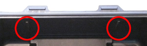
- It has "flanges" on the interior that act as a support for the board (see following image)
The first thing I did when fitting the board was to measure the case interior again. I had the specifications from the manufacturer, but as the old saying goes, "Measure twice and cut once".
Once I had the exact measurements of the interior, I marked and cut a piece of 1/4" brown particle board to fit (Do not use 3/8" material. It is too thick and your components will not mount correctly). I used a compass and jigsaw to round the corners of the board to fit.
(I had originally intended to use a sheet of black Plexiglass for the board surface. However cutting the number of holes etc that are required would have meant having it professionally done or risk shattering a lot of expensive plexi. As a "phase 2" I may use the current board as a template and have an Aluminum or Plexiglass sheet professionally milled as a replacement.)
Next, I used a yard stick to mark off the location of all the components etc on the board surface and began drilling and fitting pieces.

When drilling or cutting out holes for components, it is important to use a flat razor blade (like those used in box cutters etc) to "shave" the holes on both sides. When cutting or drilling, a lip is created around the hole that can throw the fit of the components off.
I HIGHLY recommend that you cut and fit ALL of your components before you attempt to wire anything up.
Step 2: Wiring, wiring, and more wiring...
And so the fun begins... The wiring. This project uses a LOT of wire! Plan on spending a LONG time on the wiring, unless you have extensive experience. This is not particularly technical work but it is tedious and attention to detail is important.
- The first thing I did was wire the 6 DB-25 Female connectors that will be mounted in the board. This particular type (see parts list), uses crimp on connectors rather than soldered connections. (I found this to be VASTLY easier than the soldered type. If you have extensive experience with soldering in close quarters, by all means feel free to substitute those connectors. The price is the same. I was going for easy and reliable.)
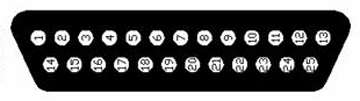
If you are looking at the connector from the front, the black wire (negative) would be in position 1 (see picture above). If you were looking at this from the back (like when you wire it) it would be where position 13 is on the diagram. It does not really matter where you put this as long as you do ALL OF THEM THE SAME (including the connectors on the remote fire stations). I did it this way so the "first" pin was always the negative and then counted up from there for the positives. This also gives us 12 positives per "row".
I precut SOLID CORE 22 gauge wire in lengths of 18". (Braided wire will work also but for this type of connector, solid core worked better for me) I cut 24 Red (positive) and 1 Black (negative) for each of the 6 connectors. (138 red, 6 black). The beauty of the DB-25 connectors is that you have 24 circuits per connector that share 1 common ground / negative.
- Once all 6 connectors were wired I mounted them to the board using the Standoff screws (jack screws, see parts list). I also mounted the 6 way selector switch, the red fire light, the green continuity light, the 2 - 12 position terminal strips (use gel superglue), and the 2 key switches.

- Next I wired the 6 DB-25 connectors to the terminal strip. There are 24 red wires per connector and 24 positions on the terminal blocks. Looking at the board from this direction, (as seen in the above picture) the first red wire on each connector (the one immediately next to the black wire) was run to the first terminal (the one on the far left). The next red wire (going left to right) was run to the second terminal. Rinse and repeat until all 24 are wired. When your done, each terminal should have six wires run to it (each of the six wires should be from a different DB-25 connector)

As you can see from the above picture, I routed the wires around the other board components as best I could and tried to keep things neat. This is another reason I used solid core wire for this stage instead of braided wire. Solid core wire stays where you bend it.
- You will note that the 6 way switch has 12 positions on the outer ring and 2 on the inner ring. This is because the switch has 2 poles. You could just as easily use a single pole 6 way switch, but this is what Radio Shack had so that’s what I bought. Essentially 6 of the outer posts connect to each of the inner posts. What I did was put the switch in position 1, and then used my volt meter to see which outer post represented that position.
To do this I picked at random which center post I was going to use and connected one lead from my volt meter. I then touched each of the outer ring posts until I found the one that was "hot" when the switch was in position 1. When doing this, set your meter on it’s lowest Ohms setting (in my case Rx1)
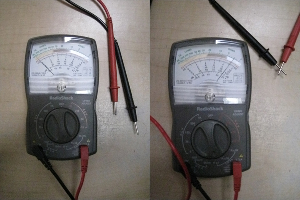
You will note that when the leads to not touch, the meter reads 0. However when the leads touch (or a circuit is completed) the needle jumps. When you touch the leads to the posts on the switch as described above, the needle will "jump" when you are on the correct outer post. It is important that all of your tests use the same center post. Once you find the outer posts for position 1 and 2 you will know where 3,4,5, & 6 are.
I then wired a 4" piece of Black 22 gauge braided wire to each of the 6 outer posts and the 1 center post I had identified. (Note when soldering, braided wire is MUCH easier to use)
(Sorry for the lousy picture)
- The next step is to assemble the 24 continuity LED’s. There are 2 parts and they are extremely easy to assemble. First take a LED holder and remove the rubber "plug / stopper" from it’s base. (You will note that the plug has 2 small holes, the LED posts go through these) Now insert an LED into the holder and then slide the plug over the LED posts and into the holder until it is snug.
Once you have all 24 assembled we need to attach lead wires to each. You will not that one of the LED posts is longer than the other. This is to indicate which is positive and which is negative. (LED stands for Light Emitting Diode. A Diode by definition will only allow current to pass in one direction. IE if you wire them wrong they will not light up) The longer post is the positive lead. The power will need to flow into the positive lead and out the shorter negative lead. Solder a 12"-18" Red 22 gauge braided wire to each of the long posts and a 12"-18" Black 22 gauge braided wire to each of the short posts. (NOTE: I shortened the leads on my LED’s so they would not stick out so far. If you trim yours, be sure to keep one longer than the other so you know which is positive) I find that it is easiest to solder the wires to the leads if I first fill the braided wire with solder and then place the wire on the lead and reheat the solder.
Once all the leads are attached, wrap each LED’s posts in electrical tape to ensure nothing shorts out. Wrap one lead entirely by itself and then continue around the second post. Do not tape around both at the same time until one lead has been wrapped by itself or you will short them out.
- Now we need to wire the 24 push button switches. Again we need to solder a 12"-18" 22 gauge braided wire to each post of the switch (1 red 1 black). It does not matter which post you attach the red / black wires to. We do not need to wrap the posts on the switches because they are short enough and far enough apart that they can not short out.
- Once all of the LED’s and switches are wired we need to mount them. This should be fairly straightforward. Simply remove the nuts from each, insert them into a hole, and attach the nut from the other side. (NOTE: The switches are very "shallow" and use plastic nuts. DO NOT over tighten them. Just get them snug. This is the part that will give you grief if you do not "shave" the holes as described earlier)
I recommend that you mount the LED and switch for position 1 and then wire the negative leads (black) to the terminal strip location we designated as "1" in step number 3. Then mount the LED and switch for position 2 and wire them to position 2 on the terminal strip. Rinse repeat.
I would also take this opportunity to mount the 2 - 2 Position Dual-Row Barrier Strips before all the parts and wires get in the way. Simply use a liberal amount of gel super glue.

- Ok... now all of your parts are mounted and there are enough wires going everywhere to give you a serious migraine. Next we need to connect everything together.
First we will work on the LED’s. We need to bundle the positive leads from the LED’s. First cut 4 x 18" length of Red 22 gauge braided wire and strip one end. Now pull the leads from the 12 LED’s on the left side of the board (6 from the top 6 from the bottom) and use a wire nut to connect the 12 leads and one of the 18" lengths of Red wire. Repeat this procedure for the right side.
We now need to repeat this process for the switches. Bundle the 12 on the left together and then the 12 on the right. You should now have 4 bundles (2 LED and 2 Switch) each with an 18" lead coming from each of the wire nuts.
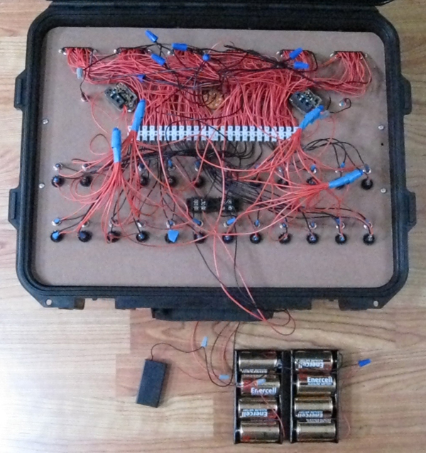
- Now we will connect the LED’s and switches to the key switches, power LED’s and the power supplies. First let’s look at where the power will attach:

As you can see from the labels, we have 2 power supplies. One is 3 volts and the other is 12 volts. The 3 volt supply (2 AA batteries) is for the continuity tests and the 12 volt (8 D batteries) supply is for the actually firing.
We need to connect a 18" length of Red 22 gauge braided wire to the positive lead of the 12 volt supply at the top. Now we need to run the other end of that wire to one of the terminals on the left key switch (if looking at the back of the board). Next we need to run the 2 18" leads coming from the SWITCH wire nuts in step 8 to the other terminal on the same key switch. We also want to connect the positive lead from the red indicator LED next to the key switch to the same terminal.

Now repeat this process for the LED leads. Connect to the positive on the 3 Volt supply, etc.
- We now need to connect the black (negative) leads on each DB-25 connector to their corresponding OUTER post on the 6 way switch. (see step 4) Simply use a wire nut to connect each pair together.
- Now run an 18" black 22 gauge braided wire from the 3 volt negative post and the 12 volt negative post. Connect these 2 wires, the black lead from the CENTER post on the 6 way switch and the black leads from each of the 2 power LED’s. (5 wires total) Connect these together with a wire nut.

- The final step is to actually hook up your power supplies. For the 3 volt supply I used a 2 x AA battery holder. For the 12 Volt supply I used 2 - 4 x D battery holders. You will need to "daisy chain" the two D battery holders together. To do this attach the positive lead (red) from battery holder #1 to the negative lead (black) on battery holder #2. Use a wire nut to hold them together.
Now cut 2 x 24" red 22 gauge braided wires and 2 x 24" black 22 gauge braided wires. Use wire nuts to connect 1 red lead to the red lead on the AA battery holder and 1 black lead to the black lead on the AA battery holder. Repeat this process for the D battery holders. (It is important to use long leads for this so you can lift your board out of the case without pulling the battery holders out)
Now we need to connect the leads to the appropriate terminals on the terminal block. (see image in step 9)
|
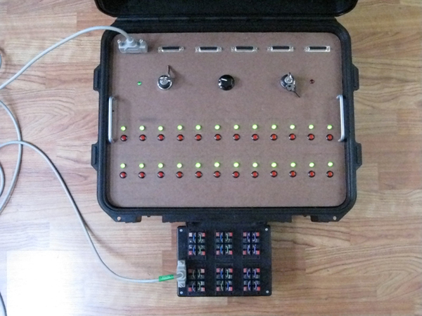
Here is what the board looks like fully assembled. You will note that I attached some cabinet handles to either side to make pulling the board in and out a little easier.
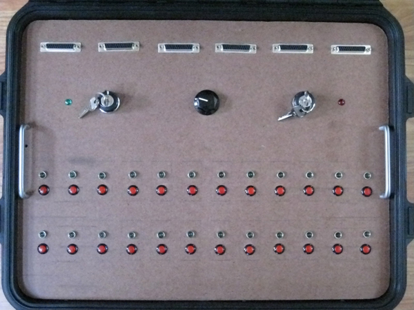
This next image shows the board with both keys on (NOTE: You should never have both keys on when you have fireworks attached. Use the green key for continuity testing and the red key for firing)

This next image shows the board doing a continuity test while hooked up to a remote fire control board. (NOTE: for testing I have shorted out each station on the remote fire board with wires to emulate having good e-matches attached.)

|
The remote stations are extremely easy to construct, but time consuming.
- For each station you will need to wire a DB-25 connector as described above.
- Next you will need to cut out 6 slots for the speaker connectors in the lid of each project box as well as a hole for the DB-25 connector. There is actually a "mark" on the bottom of the lid the exact size of the DB-25 connector, so that is easy to do.
NOTE: I used a Dremel with a cutting bit, not a blade, to make all the cuts. You could also use a router or other rotary tool. The plastic will tend to smoke when cutting so you may want to use a face mask. You should also do this step outside or in a well ventilated area. This step makes a lot of very fine plastic dust etc so I would not advise doing this indoors. Vary the speed of your rotary tool to find the ideal setting for cutting. Too fast or too slow and it will be harder than it needs to be. I did not use a "saw" or blade as this tended to make irregular cuts etc. Also the plastic, while durable, can crack so you want to avoid sudden impact or "catching" which some blades may do in this material.
- After cutting the holes, mount the speaker connector blocks (use the gel superglue again) and mount the DB-25 connector.
- Connect a #16 - #14 AWG Female Disconnect to each of the red leads on the DB-25. You will need to cut 24 black 22 gauge braided wires and attach these terminals to one end of each of these as well. (I got these at Home Depot)

- Connect the leads to the speaker connector blocks.
- Use a wire nut to connect all of the black wires together (including the one from the DB-25) NOTE: I grouped the black leads into 4 groups then connected those to the DB25 black lead. While not elegant this was faster & easier.

Next connect each red lead from the speaker terminals to the appropriate red lead on the DB25 connector.
The above picture is from the first one I did so it is kind of Frankensteined together. But you get the idea. I did not directly connect the leads from the DB25 connector to the terminals because I wanted to be able to separate the components later without cutting the leads on the DB25 connector. Again, while this is in no way elegant, I felt it was better and easier.
|
Our fireworks display was the best one so far. The fire control board performed as expected though I would mention a few caveats:
- You need to be careful and consistent in assembling your E-Matches. Too much dip and the matches "pop" rather than "burning" and you get no ignition. Too little dip and you don’t get enough out of the match to light the fuse.
- While the board works great, it is not fast to "reload". We used alligator clips run from the speaker terminals on the remote fire boards to the leads on the E-Matches. The E-Match head was in turn held against the fuse using another clip. If you are going to use this board for a show that does not require rapid reloads then it works great. Due to the volume of mortars we fired we found that it was not the most efficient system. However it worked FANTASTIC for setting of cakes etc. These are "grouped" fireworks that have 12-30 smaller mortar shots and fans in a large block. Since we did not need to reload these, we could set up the show with the cakes pre-wired to the fire control system and then just fire them at will.
- Take time to plan your show ahead of time and do all the prep work in advance (wiring, etc.) you do not want to be mid show and have to stop for 15-20 minutes to hook up a bunch of leads and E-Matches.
We will definitely be using this board again in 2009 for all of our "single shot" stations such as cakes, packs, etc. Because we shoot so many mortars and re-use each station several times we will continue to fire these manually (blow torches).
If you are doing a show that does not require re-loading or can accommodate the reload time, then this is a GREAT solution.
|
If you have any questions or comments about this project, please feel free to email fcb@necranom.com
Please use the subject "FIRE CONTROL BOARD" in your emails.
|
|